
Features
- Capable of holding up to 4 maps.
- Maps switchable using on-board jumpers.
- Quality double-sided through hole plated boards assembled to the highest standards.
- Designed to use the "double-up" (both chips programmed the same) rather than odd/even (need to split files up).
- Indicator LEDs on board to show which map is selected.
- All boards fully tested
- Supplied with full fitting instructions

FAQs
Which SR's will the boards work in?
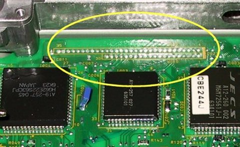
They are designed for S13 SR20's - turbo or naturally aspirated. This includes 180SX, Silvia, U13 Bluebird, GTiR Pulsar RNN14 and N14 Pulsar (68C00 ECU). People in the USA have also used them successfully on the S13 KA24DE engine. They may work on other models of SR20 from around the same vintage. If the ECU uses the same style connector they may work (NOT S14). Please note that very late S13's may have an ECU which is incompatible - it will have a 69Fxx designation instead of 50Fxx. These use a different connector to the older ECU's - see photo.
Will this allow me to tune my SR in "real time"?
The short answer is no. Tuning in "real time" requires dedicated hardware and software. Tuning is usually done using a package such as the popular "ROM Editor" on a PC to create the modified maps. These are then programmed into the EPROM chips using an EPROM programmer and fitted to the daughterboard.
Our boards are used by many tuners to program in real time but this involves using a 16 bit EPROM Emulator (or twin 8 bit emulators). An emulator consists of hardware which is plugged into the daughterboard (where the EPROMs are normally fitted). Software is then used on a laptop which loads your maps into the emulator. So to the ECU it looks just like you have a set of normal EPROMs fitted. The tricky part is that the emulator allows you to see which locations are being accessed and also to change the data while the engine is running.
We do not sell emulators - they tend to be rather expensive when talking 16 bit. Instead we have developed our own real-time tuning system. No emulator required. Lookee here!
How involved is the fitting process?
You will need reasonable electronic soldering skills and a suitable soldering iron. To fit the new header the pads on the motherboard need to have the solder removed. This should really be done using a proper vacuum de-soldering tool. If you don't have one it's best to give the job to someone who has. Using the correct tool makes it a 2 minute job. Trying to do it without risks internally damaging the motherboard. Full fitting instructions are provided.
What else do I need to do to tune my car?
You will need a copy of the free ROM Editor (or similar map editing package).
You'll also need an EPROM programmer - these are available either built up or in kit form and run from your PC. I bought a kit from Willem in Holland and have found it to be a reliable, capable unit. You can now get these programmers at www.sivava.com and I've seen them on eBay as well.
Basic steps involved:
- Remove solder from pads on ECU motherboard and fit header (supplied).
- Move SMD jumper on rear of ECU motherboard to force the micro to use external memory (details provided with daughterboard).
- Source base maps for your ECU.
- Modify the maps using ROM Editor.
- Program your new maps into ROM chips using an EPROM programmer.
- Fit the chips to the daughterboard and plug the daughterboard into the header on the motherboard.
- Drive the car and see how she goes!
What other chips can be fitted?
We now use only "flash" erase chips (29F010). These are electrically erased by the EPROM programmer. These will allow 4 maps and don't require a UV eraser. UV erase chips can still be used in the boards - including the smaller ones. This just results in less maps being available. 27C512's will allow 2 maps. 27C256's will allow only a single map.
Why are there 2 chips?
The SR20 ECU uses a 16 bit data bus. The EPROM's used are 8 bit devices - they are set up so that the upper 8 bits are supplied by one chip and the lower 8 bits from the other chip. 16 bit EPROM's could be used but the are relatively expensive (and more difficult to source) compared to 8 bit chips.
How can I switch maps now that you don't sell map switchers anymore?
If you wish to rig up your own switching device then you can select the maps using a simple binary sequence on the address pins of the 4 pin connector of the daughterboard. It's just a plain “Molex KK” style connector - 0.1” pitch.
| 00 = map 1 |
| 01 = map 2 |
| 10 = map 3 |
| 11 = map 4 |
Pin assignments:
| 1 = VCC |
| 2 = GND |
| 3 = A0 |
| 4 = A1 |
Pin 1 has the square pad on the board.
Or if you only want 2 maps then you could simply wire a switch across jumper JP1 to switch from Map 1 to Map 2. You could use a microswitch on the throttle if you wanted one “normal” map (Map 1) and then a different map (Map 2) for nitrous etc. :)
Prices and ordering available on our shopping cart